Why Roller Shutter Door Motors Still Rely on a Basic Micro Switch
In simple terms, the control logic for a roller shutter motor works as follows: pressing the "up" button causes the motor to rotate in the forward direction until the shutter is fully retracted to the top; pressing the "down" button causes the motor to rotate in reverse until the shutter reaches the bottom. While the user is primarily concerned with whether the shutter stops at the correct position, engineers must address a more fundamental question: how is it determined that the shutter has actually reached its intended destination? This is precisely why a basic micro switch is integrated into the roller shutter motor's control system.
Housed within the shutter’s limit witch assembly, the micro switch is actuated by a cam or a limit nut mounted on a threaded adjustment rod. It serves as the trigger that determines the exact moment the motor’s power is cut off. Although the cost of such a component is negligible in the context of the entire roller shutter system, its failure can lead to serious consequences—such as the shutter over-retracting, failing to close completely, or the motor stalling and burning out its windings—none of which can be overlooked. This article explores the specific role of the micro switch within a roller shutter motor control system and explains how the limit mechanism translates the multi-meter travel distance of the shutter into a precise switching action, providing a deeper understanding of its function.
What a Basic Micro Switch Really Does in a Door Motor
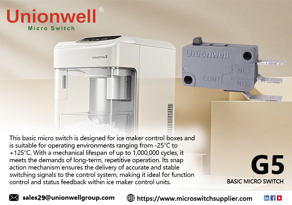
A basic micro switch is a "snap action" mechanical switch: an external force is applied to a spring mechanism via an actuator; once the mechanism crosses a critical threshold over a very short distance, the contacts switch instantaneously, accompanied by a distinct "click." In a roller shutter motor, the micro switch primarily serves to "confirm the endpoint." The upper limit confirms that the shutter has been fully retracted onto the reel and has ceased upward movement; the lower limit confirms that the bottom rail has made contact with the ground, ensuring the door is fully closed; and a safety-limit position provides a clear electrical signal if an anti-drop device is triggered, the clutch disengages, or a safety edge (sensing strip) is compressed. Common to all these functions is that they are passive, binary (on/off), and operate independently of any firmware.
This is precisely why it has not been replaced: a basic micro switch requires only a physical displacement to function. It remains operational even during a power outage, a controller freeze, or a firmware failure. For irreversible mechanical risks—such as a door rolling up too far—it operates independently of any software-based verification. Its practical value far exceeds its cost, making it an irreplaceable industrial micro switch.
How the Limit Mechanism Converts Door Travel into a Switch Action
The limit mechanism addresses a conversion challenge: translating the linear travel of a door curtain—which can span several meters—into a displacement of just a few millimeters at an actuator, which then triggers a switch. Tubular motors and external shutter operators employ two different approaches to achieve this:
- In a tubular motor, the limit mechanism is located at the motor head. It consists of a threaded rod that rotates with the output shaft, carrying a limit nut equipped with an adjustment screw. As the door curtain moves upward, the nut travels along the rod until it reaches a preset position, where it pushes against the lever of a micro switch, cutting off power to the motor. The distance the door curtain travels per full rotation of the adjustment screw is determined by the pitch of the threaded rod and the gear reduction ratio.
- For an external shutter operator, the limit mechanism is housed in a separate, compact unit containing a threaded rod fitted with several cams, each corresponding to a specific switch. One cam triggers the "up" switch, another the "down" switch, while one or two additional cams serve as secondary limits or, in the case of fire-rated shutters, as intermediate stop positions.
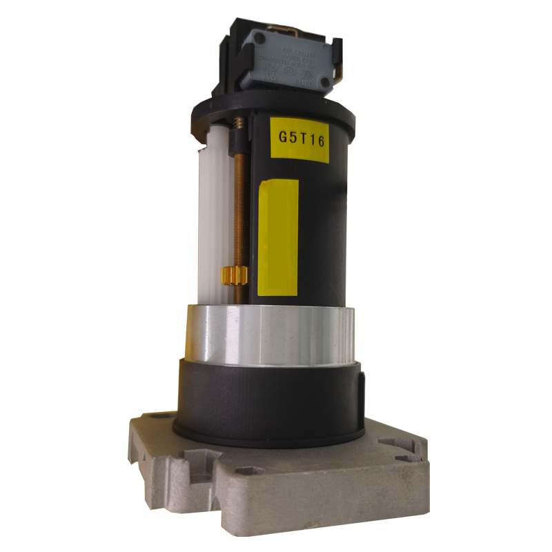
Consequently, the precision of the limit mechanism is determined by the lift and slope of the cams, the pre-travel and differential travel of the switches, and the backlash between the threaded rod and the nut. Given a total door travel of two to three meters, the repeatability of the stopping position is typically controlled to within a dozen millimeters or so; in terms of the switch itself, this means the actuation point must remain stable within a range of just a few tenths of a millimeter.
Why the Up and Down Limits Must Be Two Independent Switches
Can a single switch be used to control both the upper and lower limits? No—and this is not merely a matter of cost.
- The upper and lower limits correspond to two opposite directions of rotation and two distinct mechanical endpoints; therefore, the cams must be positioned at opposite ends of the travel range. Using a single switch would mean that both cams actuate the same contact point, making it impossible to distinguish the direction of movement. Furthermore, if the contacts of a single switch were to weld together, both the upward and downward travel would lose their protection simultaneously.
- Once separated, the two types of failure consequences become clearly distinct: if the upper limit fails, the door curtain continues to wind onto the reel, leading to crushed slats, derailment, and the springs being stretched to their absolute limit—a scenario that typically requires dismantling the entire reel assembly to repair. If the lower limit fails, the motor continues to run until the bottom rail is pressed firmly against the ground; the process only stops when the friction clutch slips or a thermal protector trips. Common repercussions include a rise in winding temperature, deformation of the door assembly, and wear on the clutch plates.
The cost of adding an extra switch provides a robust, independent layer of protection that does not rely on the operational integrity of the primary limit switch—a standard practice for industrial doors and fire-rated rolling shutters.
Safety Functions Beyond Limit Detection
Beyond standard limit detection, rolling shutter door motors incorporate additional position-sensing mechanisms. While these may utilize the same types of switches, their underlying logic differs significantly:
- Anti-drop systems are a prime example. Designed for industrial doors and fire-rated rolling shutters, these mechanisms engage—locking or hooking the door—in the event of excessive descent speed, spring failure, or the breakage of suspension components. Typically, these devices are equipped with a micro switch that signals the controller when the mechanism has triggered, prompting an immediate system halt and alarm.
- Safety edges represent another critical function. Integrated into the bottom rail of the door, a safety edge consists of either a conductive rubber strip or a series of connected micro switches. If the descending door encounters a person or object, the resulting deformation of the safety edge closes or opens an electrical circuit, causing the controller to reverse the door's movement within tens of milliseconds. It is essential that the response time remains consistent across the entire length of the safety edge; otherwise, the system could become unreliable—for instance, responding effectively when an object is pressed against the left side, but failing to react on the right.
- Fire-rated rolling shutters also require specific position monitoring. Upon activation of the thermal release mechanism, the door must descend in two stages: first, it stops at a height of approximately 1.8 meters above the floor to facilitate personnel evacuation, before descending fully to seal the opening. Switches are required to confirm both the intermediate and fully closed positions; the controller will not proceed to the next stage of the sequence unless it receives a confirmation signal for the current step.
The Parameters That Determine a Ten-Year Lifespan
When translating these operational scenarios into technical specifications, it becomes clear that while only a few key parameters truly matter, each one must fall within a precise, defined range:
|
Parameter |
Typical Range |
Significance in Roller Shutter Limit Switches |
|
Operating Force (OF) |
Limit switch applications usually take 50–150 gf |
Ensures the cam can press it smoothly while preventing false triggering caused by vibration |
|
Pretravel (PT) |
0.3–0.6 mm |
Determines the trigger lead time and the consistency of the stopping position |
|
Overtravel (OT) |
≥ 0.5 mm |
Absorbs overshoot caused by door inertia |
|
Movement Differential (MD) |
≤ 0.1 mm |
Repeatability precision; determines whether each stopping position remains consistent |
|
Contact Rating |
Signal grade: 0.1A / 48VDC; Power grade: 20A / 250VAC |
Indicates whether it directly breaks/switches the motor current |
|
Contact Resistance |
Initial ≤ 50 mΩ, Insulation ≥ 100 MΩ |
Reliability and credibility of the signal loop |
|
Dielectric Strength |
1500 VAC, 1 min |
Insulation margin under inductive loads and humid environments |
|
Mechanical / Electrical Life |
1,000,000–10,000,000 cycles / 50,000–100,000 cycles |
Service life in years converted based on daily operating frequency |
|
Operating Temperature |
-25 to +125°C |
Motor compartment temperature rise, summer sunlight exposure, and winter low temperatures |
Conclusion
While a basic micro switch may be a low-cost component in a machine’s overall bill of materials, it guards the only irreversible boundary of the entire system—ensuring the door curtain does not over-travel and that the door itself closes securely. Its reliability stems from its simplicity: it requires no trust in software. When the cam presses down, the contacts open, and the motor loses power. By understanding how parameters like pre-travel, over-travel, and differential travel dictate the consistency of the stopping position, one can see why—even in an era dominated by electronic limit switches—the mechanical micro switch remains the final line of defense.
For door system manufacturers, the criteria for selecting a basic micro switch are a narrow distribution of operating points and robust batch traceability. An industrial micro switch with a stable operating point—sourced from a micro switch supplier willing to provide force-travel curves and batch-specific data—saves significant labor hours otherwise spent on individual unit calibration during production, and helps avoid the after-sales service tickets that arise when a door fails to stop in the correct position.
Top 5 Best Micro Switch Types for Home Appliance
Related Article